Why GD&T Matters in Machined Components
Understanding Geometric Dimensioning & Tolerancing for Better Manufacturing and Inspection
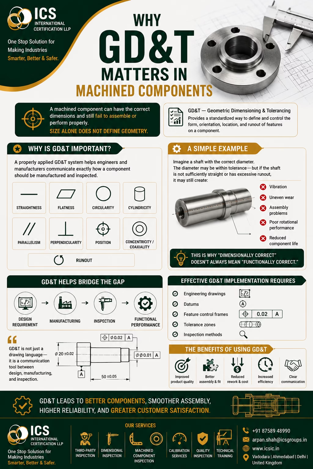
In precision manufacturing, a component can have all its basic dimensions within tolerance and still fail to assemble or perform properly.
Why?
Because size alone does not completely define the geometry of a component.
This is where GD&T — Geometric Dimensioning and Tolerancing — becomes important.
GD&T provides a standardized method for communicating and controlling the form, orientation, location, and runout of features on engineering drawings. When properly applied, it helps connect design requirements with manufacturing and inspection.
A component can be dimensionally correct and still be functionally incorrect.
What Is GD&T?
Geometric Dimensioning and Tolerancing (GD&T) is a symbolic language used on engineering drawings to define allowable variation in the geometry of manufactured features.
Traditional dimensional tolerances primarily control size.
GD&T can additionally control characteristics such as:
- Form
- Orientation
- Location
- Profile
- Runout
This allows designers to communicate functional requirements more clearly and gives manufacturing and inspection teams a common technical language.
Why Is GD&T Important for Machined Components?
Machined components frequently contain features that must interact precisely with other components.
Examples include:
- Shafts
- Housings
- Flanges
- Bushes
- Gears
- Bearing seats
- Precision plates
- CNC-machined components
- Mechanical assemblies
Simply verifying length and diameter may not be sufficient.
A shaft, for example, could have the correct diameter but still have excessive straightness deviation or runout.
The result could include:
❌ Vibration
❌ Uneven wear
❌ Assembly difficulties
❌ Poor rotational performance
❌ Reduced component life
This demonstrates an important principle:
Correct size does not always mean correct geometry.
The Four Main Categories of GD&T
GD&T controls can broadly be understood through several categories.
1. Form Controls
Form controls define the shape of an individual feature without directly referencing a datum.
Common examples include:
- Straightness
- Flatness
- Circularity
- Cylindricity
These controls are important when the shape of a surface or feature itself affects functionality.
2. Orientation Controls
Orientation controls define how a feature is oriented relative to a reference, often a datum.
Common examples include:
- Parallelism
- Perpendicularity
- Angularity
For example, a surface may have the correct dimensions but still not be sufficiently perpendicular to another critical surface.
3. Location Controls
Location controls define where a feature should be positioned.
A key example is:
Position
Position tolerance is widely used to control the location of features such as holes.
For a multi-hole flange, for example, the hole diameters may all be correct while their locations are not sufficiently controlled.
This can create assembly problems.
4. Runout Controls
Runout controls are particularly important for rotating components.
They can help control variations of a surface relative to a specified datum axis during rotation.
Runout may be important for components such as:
- Shafts
- Rotors
- Hubs
- Bearing components
- Rotating mechanical parts
Excessive runout can contribute to unwanted vibration or uneven performance depending on the application.
What Is a Datum?
A datum provides a reference from which certain geometric requirements can be established.
Datums are particularly important in GD&T because many geometric tolerances are meaningful only in relation to a reference system.
A typical machined component may use:
- A primary datum
- A secondary datum
- A tertiary datum
Together, these references can establish a consistent framework for manufacturing and inspection.
Why does this matter?
Imagine inspecting the same component from different reference points.
If the inspection setup is inconsistent, measurements may not provide a meaningful comparison with the design intent.
A properly defined datum reference system helps establish how the component should be oriented and located for relevant requirements.
Feature Control Frames
One of the most recognizable elements of GD&T is the Feature Control Frame (FCF).
It communicates information about a geometric requirement using standardized symbols and values.
Depending on the requirement, a feature control frame can communicate:
- The geometric characteristic
- Tolerance value
- Applicable modifiers
- Datum references
This allows complex geometric requirements to be communicated in a compact and standardized form.
A Simple Machined Shaft Example
Consider a precision shaft.
Its drawing specifies the required diameter.
During inspection, the diameter is found to be within the specified size tolerance.
At first, everything appears acceptable.
However, imagine the shaft also has excessive runout.
The shaft may still experience:
- Vibration during rotation
- Uneven contact
- Increased bearing loading
- Premature wear
- Assembly or functional issues
This is why dimensional inspection should consider the actual requirements specified on the engineering drawing, rather than checking only basic dimensions.
GD&T and Conventional Dimensional Tolerances
There is an important difference between size tolerances and geometric tolerances.
Dimensional Tolerance
Controls how much a dimension may vary.
For example:
Ø20.00 ± 0.02 mm
This controls the size of the feature within the specified tolerance.
Geometric Tolerance
Controls characteristics such as:
- Shape
- Orientation
- Location
- Runout
A component may satisfy the size tolerance while failing a geometric requirement.
Therefore:
Dimensional tolerances and geometric tolerances often work together to define functional requirements.
Why GD&T Helps Manufacturing
GD&T can improve communication between design and manufacturing teams.
A clearly defined drawing can help manufacturers understand:
- Which features are critical
- Which surfaces act as references
- How much geometric variation is acceptable
- Which features require precise positioning
- What inspection characteristics need to be verified
This can reduce ambiguity and help manufacturing teams focus on functional requirements rather than unnecessarily tight tolerances.
Why GD&T Helps Inspection
GD&T is equally important for inspectors.
An inspector must understand not only what dimension to measure, but also how the requirement is defined and referenced.
Inspection may involve appropriate equipment and methods such as:
- Vernier calipers
- Micrometers
- Height gauges
- Dial indicators
- Bore gauges
- Surface plates
- CMMs
- Optical measurement systems
- Specialized gauges
The appropriate equipment depends on the feature, tolerance, geometry, measurement capability, and applicable requirements.
GD&T and Dimensional Inspection
When inspecting a GD&T-controlled component, the inspector should first understand the drawing requirements.
The inspection process may involve:
Step 1: Review the Drawing
Confirm the correct drawing revision and identify relevant GD&T requirements.
Step 2: Identify Datums
Understand the datum reference framework.
Step 3: Identify Critical Features
Determine which features have geometric controls.
Step 4: Select Appropriate Equipment
Choose suitable inspection equipment for the required characteristic.
Step 5: Establish the Measurement Setup
Set up the component according to the applicable inspection method.
Step 6: Perform Measurement
Measure the required characteristic according to the defined procedure.
Step 7: Evaluate Against Requirements
Compare the result with the applicable tolerance and acceptance criteria.
Step 8: Document the Result
Record inspection results and maintain traceability where required.
Common GD&T Inspection Challenges
GD&T provides powerful tools, but incorrect interpretation can lead to incorrect inspection results.
Common challenges include:
❌ Misunderstanding Datums
Using the wrong reference system can lead to an incorrect inspection setup.
❌ Checking Only Size
A component may meet its dimensional tolerances but fail its geometric requirements.
❌ Using an Unsuitable Measuring Method
Not every GD&T characteristic can be reliably evaluated using a simple measuring instrument.
❌ Incorrect Drawing Interpretation
Misinterpreting a feature control frame can result in an incorrect acceptance decision.
❌ Ignoring Functional Intent
GD&T requirements are generally connected to how a component is intended to function and assemble.
The Importance of Proper GD&T Training
Because GD&T uses standardized symbols and concepts, proper understanding is essential.
Engineering, manufacturing, and inspection personnel may need knowledge of:
- GD&T symbols
- Datums
- Feature control frames
- Tolerance zones
- Material condition modifiers
- Basic dimensions
- Inspection methods
- Drawing interpretation
A shared understanding helps different departments communicate more effectively.
GD&T and Quality Improvement
Proper use of GD&T can contribute to better manufacturing and inspection practices.
Potential benefits include:
✅ Clearer engineering communication
✅ Better control of critical features
✅ Improved assembly compatibility
✅ More appropriate inspection planning
✅ Reduced ambiguity in drawings
✅ Reduced unnecessary rework
✅ Better understanding between design, production, and quality teams
The objective is not simply to make tolerances tighter.
Instead, GD&T can help define the right tolerances for the intended function.
Calibration and Measurement Control
GD&T inspection depends heavily on reliable measurement.
Therefore, measuring equipment should be appropriately controlled according to its intended use and applicable requirements.
Depending on the organization’s measurement system, controls may include:
- Calibration
- Verification
- Intermediate checks
- Maintenance
- Identification
- Proper storage
However, a calibrated instrument alone does not guarantee a correct result.
The measurement also depends on:
- Correct setup
- Suitable method
- Instrument capability
- Operator competence
- Environmental conditions
- Component condition
Reliable inspection requires both controlled equipment and correct measurement practice.
GD&T in CNC Machining
GD&T is particularly valuable in CNC machining because modern manufacturing processes can achieve high levels of precision.
CNC machining can produce complex components with numerous critical features.
However, the manufacturing process still needs clearly defined requirements.
GD&T can help communicate:
- Hole positions
- Feature orientation
- Surface relationships
- Shaft alignment
- Runout
- Flatness
- Perpendicularity
This helps create a common link between CAD/design intent, CNC manufacturing, and inspection.
GD&T Helps Bridge the Quality Chain
A useful way to understand GD&T is:
Design Requirement → Manufacturing → Inspection → Functional Performance
Each stage needs to understand the same technical intent.
Design
Defines what the component needs to achieve.
Manufacturing
Produces the component according to the drawing requirements.
Inspection
Verifies whether the specified requirements have been met.
Functional Performance
The component works as intended within the larger assembly or system.
GD&T helps connect these stages through a standardized technical language.
Best Practices for Using GD&T
Organizations can improve the effectiveness of GD&T by following practical principles.
📐 Use Clear Drawing Requirements
Define critical features and geometric requirements appropriately.
🎯 Use Functional Tolerances
Avoid unnecessarily tight tolerances where they do not provide functional value.
🔧 Establish Appropriate Datums
Use references that represent the functional relationship of the component.
📏 Plan Inspection Early
Consider how each important GD&T requirement will actually be measured.
🧠 Train Personnel
Ensure design, manufacturing, and inspection teams understand the relevant GD&T requirements.
📋 Maintain Drawing Control
Ensure teams use the correct approved drawing and revision.
Final Thoughts
GD&T is much more than a collection of symbols on an engineering drawing.
It is a communication system that connects design, manufacturing, and inspection.
A machined component can have:
✔️ Correct length
✔️ Correct diameter
✔️ Correct thickness
…and still fail because its form, orientation, location, or runout does not meet the required specification.
That’s why understanding GD&T matters.
Size tells you how big a feature is. GD&T helps define how that feature must exist geometrically in relation to the design intent.
Better GD&T understanding → Better manufacturing → Better inspection → Better components.
Dimensional Inspection & Quality Services
ICS International Certification LLP supports industries with professional quality and inspection services, including:
- Dimensional Inspection
- Machined Component Inspection
- Third-Party Inspection
- Fabrication Inspection
- Welding Inspection
- Visual Inspection
- Material Inspection
- Calibration Services
- Quality Inspection
- Technical Training
ICS International Certification LLP
One Stop Solution for Making Industries Smarter, Better & Safer.
📞 +91 87589 48990
📧 arpan.shah@icsgroups.in
🌐 www.icsic.in