Bore & Diameter Inspection: Importance, Methods, Instruments and Quality Control
Bore and diameter inspection is a critical part of dimensional inspection and precision manufacturing. Even a small dimensional variation in an internal bore or external diameter can affect component fit, assembly, performance, safety, and service life.
In industries such as automotive, engineering, fabrication, machining, pumps, valves, aerospace, and general manufacturing, accurate measurement of bores and diameters is essential for ensuring that components conform to engineering drawings, specified tolerances, and customer requirements.
At ICS International Certification LLP, dimensional inspection and third-party inspection services help organizations verify manufactured components against defined specifications and quality requirements.
What Is Bore & Diameter Inspection?
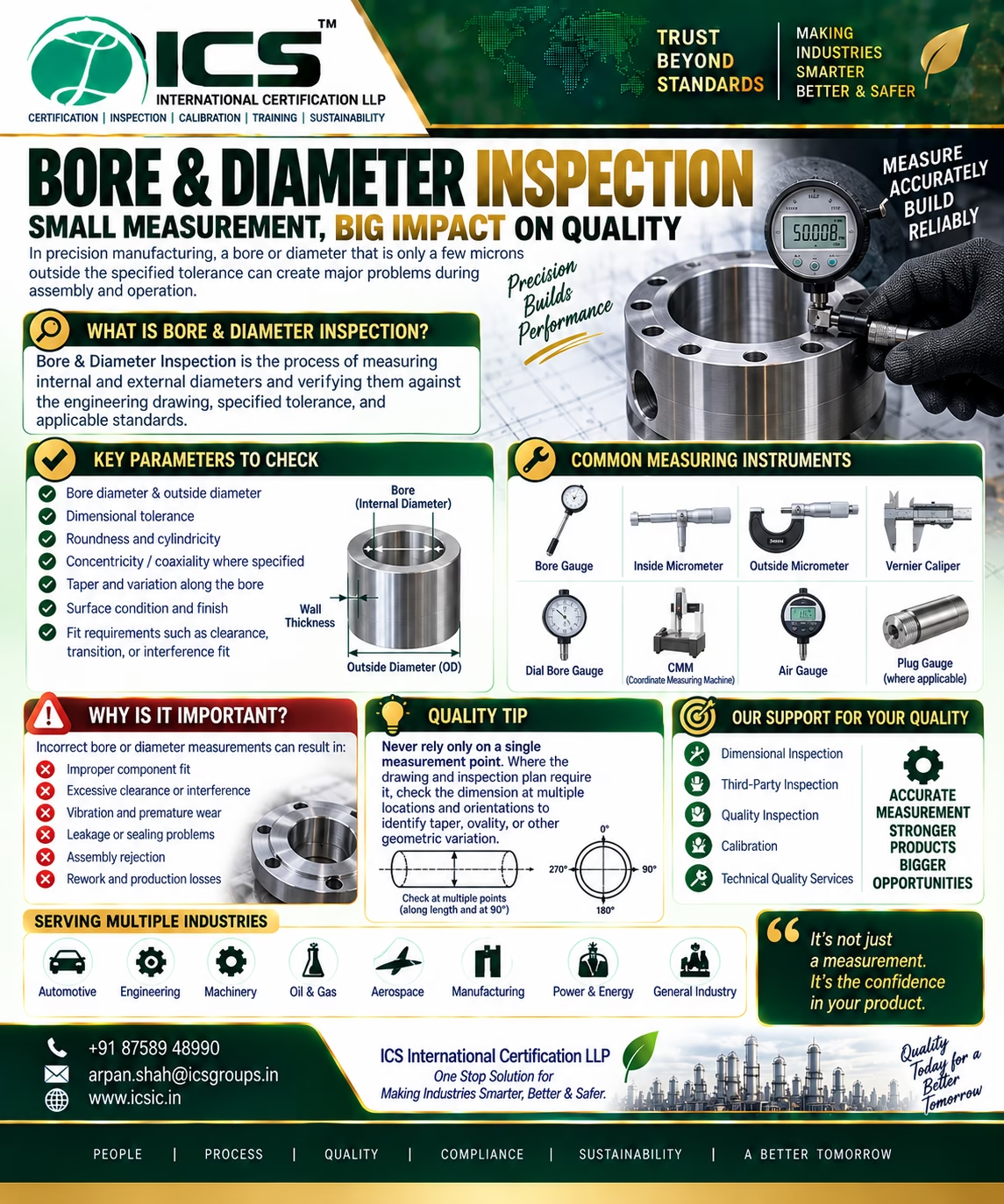
Bore & Diameter Inspection is the process of measuring and verifying the internal and external dimensions of a component against specified requirements.
A bore generally refers to an internal cylindrical diameter, such as the hole inside a shaft housing, bearing housing, cylinder, valve body, or machined component.
A diameter may refer to either:
- Internal diameter (ID)
- External diameter (OD)
The measured value is compared with the nominal dimension and allowable tolerance specified on the engineering drawing or inspection specification.
For example, if a drawing specifies:
Ø50.00 mm ± 0.02 mm
the acceptable dimensional range is:
49.98 mm to 50.02 mm
A measurement outside this range may result in rejection, rework, or further technical evaluation.
Why Is Bore & Diameter Inspection Important?
Bore and diameter dimensions often determine how two or more components fit together.
An incorrect dimension can lead to:
- Improper assembly
- Excessive clearance
- Excessive interference
- Component seizure
- Leakage
- Increased vibration
- Premature wear
- Bearing failure
- Reduced equipment performance
- Rework and rejection
- Production delays
For precision components, dimensional accuracy is therefore not simply a measurement requirement—it can directly influence the reliability and functionality of the finished product.
Key Parameters Checked During Bore & Diameter Inspection
A comprehensive inspection may include more than simply measuring one diameter.
1. Internal Bore Diameter
The internal diameter of a machined hole is measured and compared with the specified tolerance.
This is particularly important for components designed to accommodate:
- Shafts
- Bearings
- Bushes
- Pins
- Seals
- Other mating components
2. Outside Diameter
External diameters are checked to ensure that shafts, pins, sleeves, rollers, and other cylindrical components meet their specified dimensions.
3. Tolerance
The measured dimension must fall within the tolerance specified on the drawing.
Tolerance defines the permissible variation from the nominal dimension.
4. Roundness
A bore may have the correct average diameter but still be slightly out of round.
Roundness inspection helps identify variations from the ideal circular profile.
5. Cylindricity
Cylindricity considers the three-dimensional cylindrical form of a feature.
It can be important where the bore or external diameter must maintain a consistent cylindrical shape throughout its length.
6. Taper
A bore may have different diameters at different depths.
Measuring at multiple locations can help identify taper or dimensional variation along the bore.
7. Ovality
A circular bore may become slightly elliptical rather than perfectly round.
Checking measurements at different angular orientations can help identify ovality.
8. Concentricity or Coaxiality
Where specified by the engineering drawing or applicable GD&T requirements, the relationship between different cylindrical features may also need to be verified.
9. Surface Finish
Dimensional accuracy alone may not be sufficient.
The surface condition of a bore can influence:
- Friction
- Sealing
- Lubrication
- Wear
- Mating performance
Therefore, surface finish may also be inspected where specified.
Common Instruments Used for Bore & Diameter Inspection
The appropriate measuring instrument depends on the dimension, tolerance, component geometry, required accuracy, and inspection method.
Bore Gauge
A bore gauge is commonly used for measuring internal diameters and detecting variations along a bore.
It can be particularly useful for identifying:
- Bore diameter variation
- Taper
- Ovality
Inside Micrometer
Inside micrometers are used to measure internal dimensions with suitable accuracy for the application.
They are commonly used for larger internal dimensions where appropriate.
Outside Micrometer
Outside micrometers are widely used for accurately measuring external diameters.
They are commonly used for shafts, pins, sleeves, and other cylindrical components.
Vernier Caliper
Vernier calipers can be used for general dimensional checks where the required tolerance and accuracy are suitable for the instrument.
However, for tight-tolerance applications, a more precise measuring instrument may be required.
Dial Bore Gauge
A dial bore gauge can provide comparative measurements and help identify dimensional variation within a bore.
Plug Gauge
Plug gauges can be used for checking whether an internal feature falls within specified limits, particularly in production environments where fast GO/NO-GO verification is required.
Air Gauge
Air gauging can provide highly sensitive dimensional measurement for suitable applications and is commonly associated with precision internal-diameter inspection.
Coordinate Measuring Machine (CMM)
A CMM can be used for detailed dimensional and geometric inspection where complex components or multiple dimensional characteristics need to be evaluated.
Why One Measurement May Not Be Enough
One of the most common mistakes in dimensional inspection is taking a single measurement and assuming that it represents the complete condition of the bore.
Consider a bore that appears to measure correctly at one location.
It may still have:
- Taper along its length
- Ovality
- Local dimensional variation
- Misalignment
- Surface-related issues
For this reason, the inspection plan should define the appropriate measurement locations, orientations, number of readings, and acceptance criteria.
Multiple measurements can provide a better understanding of the actual dimensional condition of the component.
Bore Inspection Example
Suppose a component drawing specifies an internal bore:
Ø50.00 mm ± 0.02 mm
The acceptable range is:
49.98 mm – 50.02 mm
During inspection, measurements are taken at different depths and orientations.
For example:
| Measurement Location | Reading |
|---|---|
| Top – 0° | 50.01 mm |
| Top – 90° | 50.00 mm |
| Middle – 0° | 50.02 mm |
| Middle – 90° | 50.01 mm |
| Bottom – 0° | 50.04 mm |
| Bottom – 90° | 50.03 mm |
Although some readings are within tolerance, the bottom measurements exceed the specified maximum.
This could indicate dimensional variation or taper and should be evaluated according to the applicable drawing and inspection criteria.
Bore & Diameter Inspection in Machining
Bore and diameter inspection becomes particularly important after machining operations such as:
- Drilling
- Boring
- Reaming
- Honing
- Turning
- Grinding
- CNC machining
Machining parameters, tool wear, machine condition, temperature, setup, and operator technique can influence final dimensions.
Regular dimensional inspection can help identify problems before large quantities of components are produced.
Inspection Before and After Machining
Dimensional inspection can be performed at different stages of manufacturing.
Before Machining
Inspection may establish the condition of the incoming or semi-finished component.
During Machining
In-process measurements can help identify dimensional drift and allow corrective action.
After Machining
Final inspection verifies whether the finished component meets the drawing and specified acceptance criteria.
This approach helps reduce the risk of discovering dimensional problems only after the complete manufacturing process has been completed.
Importance of Calibration
Accurate inspection depends not only on the skill of the inspector but also on the suitability and condition of the measuring instrument.
Measuring instruments such as:
- Micrometers
- Bore gauges
- Vernier calipers
- Dial indicators
- CMMs
- Plug gauges
- Other precision instruments
should be appropriately controlled and calibrated or verified according to the organization’s requirements and applicable standards.
An instrument that is out of calibration can produce unreliable measurement results.
Therefore:
Accurate component + inaccurate instrument = unreliable inspection result.
Measurement Conditions Matter
Environmental and measurement conditions can also influence dimensional results.
Important considerations may include:
- Temperature
- Cleanliness
- Component condition
- Instrument condition
- Measurement technique
- Alignment
- Contact pressure
- Operator skill
For precision measurements, controlling these factors becomes increasingly important.
Bore & Diameter Inspection and GD&T
Modern engineering drawings may use Geometric Dimensioning and Tolerancing (GD&T) to control not only size but also the form, orientation, and location of features.
Depending on the drawing, bore-related requirements may involve characteristics such as:
- Position
- Cylindricity
- Roundness
- Straightness
- Perpendicularity
- Coaxiality-related requirements
- Profile
Therefore, an inspection should not focus only on the numerical diameter if additional geometric requirements are specified.
Common Problems Found During Bore Inspection
Some common dimensional issues include:
Oversized Bore
The bore is larger than the specified upper limit.
Possible consequences include excessive clearance and poor component fit.
Undersized Bore
The bore is smaller than the specified lower limit.
This can cause interference, assembly difficulty, or component seizure.
Tapered Bore
The diameter changes along the length of the bore.
Oval Bore
The bore is not sufficiently circular.
Misaligned Bore
The bore may not be correctly positioned or aligned relative to another feature.
Surface Damage
Scratches, scoring, burrs, or other surface conditions may affect the functional performance of the bore.
Benefits of Professional Dimensional Inspection
A systematic bore and diameter inspection process can help organizations:
✅ Verify drawing compliance
✅ Reduce dimensional rejection
✅ Detect machining variation
✅ Improve component interchangeability
✅ Reduce assembly problems
✅ Minimize rework
✅ Improve supplier quality
✅ Support customer inspection requirements
✅ Improve measurement traceability
✅ Strengthen overall quality assurance
Third-Party Bore & Diameter Inspection
Third-party inspection provides an independent assessment of component conformity.
Depending on the agreed inspection scope, a third-party inspector may review:
- Engineering drawings and specifications
- Inspection and Test Plans
- Material identification
- Component dimensions
- Bore and diameter measurements
- Geometrical requirements
- Surface condition
- Calibration status of measuring equipment
- Inspection records
- Final documentation
The exact scope should always be based on the purchase order, drawing, specification, applicable standards, and agreed inspection plan.
Best Practices for Bore & Diameter Inspection
For reliable dimensional inspection:
1. Understand the drawing first
Identify nominal dimensions, tolerances, GD&T requirements, and applicable notes.
2. Select the right instrument
The instrument should be suitable for the required accuracy and measurement range.
3. Verify instrument status
Ensure the measuring equipment is within its required calibration or verification status.
4. Clean the component
Remove dirt, chips, burrs, oil, or other conditions that could influence measurement.
5. Measure at appropriate locations
Use the inspection plan to determine measurement points and orientations.
6. Record actual results
Do not record only “OK.” Actual measurements provide better traceability.
7. Compare against acceptance criteria
Evaluate results against the specified drawing or applicable requirement.
8. Investigate abnormal variation
A changing measurement can indicate taper, ovality, tool wear, setup problems, or other manufacturing issues.
Final Takeaway
Bore and diameter inspection is a fundamental part of precision dimensional quality control.
A component can look perfect visually and still fail because its bore is slightly oversized, undersized, tapered, oval, or incorrectly positioned.
The combination of the right measuring instrument, correct measurement method, calibrated equipment, competent inspection, and clear acceptance criteria helps organizations achieve reliable dimensional results.
At ICS International Certification LLP, we support industries with professional Dimensional Inspection, Third-Party Inspection, Quality Inspection, Calibration, and Technical Quality Services to help verify components against specified requirements.
Need Professional Dimensional Inspection Support?
Contact ICS International Certification LLP for inspection and quality-related services.
📞 +91 87589 48990
📧 arpan.shah@icsgroups.in
🌐 www.icsic.in
ICS International Certification LLP
One Stop Solution for Making Industries Smarter, Better & Safer.